So your other choice is pin 3. You most certainly can use an internal pullup on the Arduino to simplify the wiring but we use a physical resistor as it is much easier to explain the basics of how a pull-up resistor works when you have to connect the wires yourself. 1000 / 450 = 2.22. No programming required! Thank you for the kind feedback! I can only bash my face on the keyboard for so long. Why not use pinMode(flowPin, INPUT_PULLUP) instead of a 10 ohm resistor on the signal wire? remove the next two lines and just divide flowRate by 1000. Its great to find such a well explained tutorial! i want to measure number of liters and not liters/min and also calculate the price based on price/liter.what should the code look like? The following diagram shows the pinout of the YF-S201 water flow sensor. how does that come? Since then, they have grown to become a leader in Do-It-Yourself electronics and open source technology. Programming the micro:bit V2 can be done by computer or by their intuitive app available for Android and iOS devices. Could we juste reajuste the *2.25? //System Not Flowing Water We will be using the Arduino IDE, this is available fromhttps://www.arduino.cc/en/Main/Software. else { Is there a way to mesuare how long the sensor has run, i dont need to know how much it has run, but i need to know it has run over 5 min, and then it need to send a signal to a relay, so close a valve. In the last step we extended the sensors wire harness we can now plug these jumper wires into the breadboard. On the following line we delay the code for 1000ms (1 Second) to give us time to count pulses and on the last line we disable the interrupts to stop counting. The Adafruit Feather line of Arduino compatible microcontrollers are designed with battery power and portability in mind. Thanks! 1000/450= 2.25mL. So, what is the best way to count RPM with an Arduino? } I want to write to EEPROM when the Arduino detects power down Im not sure it is ok because EEPROM cycle use is limited. Each revolution you will see the voltage on the sensor output transition from HIGH to LOW and back to HIGH again so you can monitor the falling or rising event you will still get the same count. Delay is simple and it does exactly what it says it does writing better non-blocking code is a concept that can be learned later and isnt terribly relevant to getting the basic sensor working . Detect_Rising_Edge() function is the interrupt function that is used to count the pulses generated by the Hall effect sensor. The interrupt function will be calling the Flow function so lets go ahead and add the interrupt to the setup section of code: So that last little bit may require a little more explanation: The first thing we should be clear about is on the Arduino Uno pin 2 is Interrupt 0, so both lines of code we have added are referring to the same physical pin on the Arduino. We are going to jump right in and set up the Arduino Uno and the breadboard right next to one another. Should I use ESP8266 digital pin (GPIO2) as input pin and in attachInterrupt function? We have been a supplier of Adafruit in Canada since our humble beginnings in 2012. Ted, You are correct in a sense. This section deals with the interfacing of an Arduino microcontroller to the YF-S201 Water Flow Sensor. The electric pulse will be generated due to the flow. The harness itself has a Red, Yellow, and Black wire. } While we do stock a significant number of Adafruit products, if you dont see the Adafruit product you are looking for please feel free to send us an email we will happily bring it in for you. Because we know that in one minute there are 60 seconds. After 100ml, valve closes. Just curious, regarding the interrupt configuration attachInterrupt(0, Flow, RISING). YF-S201 is a water sensor technically designed to measure the flow rate and volume of the desired fluid through the pipelines. How can I implement it into code ? When an input is floating it may hold the last value, it may flip between off and on, quite random generally not a good thing when we are trying to tell if it is on or off! Moving from an exercise in Arduino to a reliable control system would definitely involve some level of calibration thanks for the suggestions on how to accomplish this! Firstly, we will see an introduction of flow rate sensors that is why and where to use flow sensors. Just one observation, it is a little risk to assume 2.25 ml per rotation, it will depend on some other variables such as pressure, hose length and so on. It was created to make getting into these often daunting fields as easy as possible. We dont provide help with custom projects, only questions directly relating to the tutorial. The NVIDIA Jetson Nano is an in-expensive, high performance, single board computer developed specifically with artificial intelligence applications in mind. Knowing that there are 450 pulses per liter, we can then determine the flow rate over time or the total volume that has passed or both! Hello! I used ur setup and sometimes interrupts are lost Thanks, Jos. For example, valve opens, water flows and passes sensor. When an interrupt is sensed at pin D2, the Detect_Rising_Edge() routine is called and the count of pulses is incremented in Pulse_Count by one. Hey, i am working on a similar project. Should the instead be Youll need to match your units but you should be able to calculate the speed of your water using this formula. BC Robotics products in our shop: Pololu, pronounced PO-LO-LU, is an American manufacturer of quality electronic components based in Las Vegas, Nevada. flowRate = flowRate * 60; //Convert seconds to minutes, giving you mL / Minute Upload the code on the Arduino. That is: It consists of three pins: YF-S201 is a plastic body water flow sensor that has a valve, rotor, and a Hall effect sensor. Hence: In this section, we will see how to display measured water flow rate value on 162 LCD. Before we give the Arduino power it is always a good idea to go over all of the connections to make sure there are no wires in the wrong spot sometimes that can make for a very expensive mistake! But ESP runs on 3.3V while pretty much all sensors are rated for 5V or higher. I am new for arduino and i couldnt find any code like that. As Jose said, this is one of the best tutorials about getting flow sensor pulses. If you dont know how to interface a 162 LCD with Arduino, you can check this guide: Now make connections with Arduino, water flow sensor and 162 LCD according to this schematic diagram:16X2 LCDArduinoD4 D79, 10, 11, 12E7RS4VEEPOT (Middle Leg)VSSGroundVDD+5VD++5VD-Ground, Connections with Arduino and water flow sensor:ArduinoWater Flow SensorD2Signal Output5VVCCGNDGND. Not terribly useful having a 1s delay if the sketch needs to do anything else, this is blocking code. Now is the time to test the output of the above sketch of the water sensor. May want to include a buffer value as there can be a little drift in the sensor.
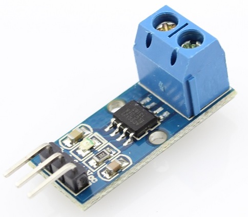
In order to measure the flow or volume of the fluid, we fix the sensor between the water inlet and outlet valves. Thanks! Helo sir can i get a code that helps the flow sensor to read the flow of pressure passing through the valve ( i mean like if the valve is completely open the sensor will detect full pressure and give out a reading of 100% likewise if its half open the sensor will detect from the pressure and give out a reading for 50% also respectively for 75% and 25%. This will give us the number of pulses generated by the water flow sensor in one second. Aside from that, it acts just like any other integer. In the end, we will see how to interface the YF-S201 Water flow sensor with Arduino and its programming in Arduino IDE.
You may want to adjust the duration the measurement is done. Now that we have finished with the hookup we need to start writing some code. how can i print how many liters passed in the sensor and how to print it on LCD? Thanks for a wonderful explanation. else { volatile int count; //This integer needs to be set as volatile to ensure it updates correctly during the interrupt process.

As discussed earlier, we need to count the output pulses of a sensor to measure the water flow rate. What happens when several signals come in at once? Definitely not doable with the current code. I know that this is not a precision instrument, but why not use the correct factor? How did yours go? We manufacture 70+ different electronic accessories and stock 2000+ unique and interesting electronics from popular brands including Arduino, Raspberry Pi, BBC micro:bit, Adafruit, SparkFun, Makey Makey and more! First of all I want to say thank you for your thorough explanation, and it was easier to understand thanks to the steps you split it. thank you. SparkFun products in our shop: 1 x Arduino Uno or compatible microcontroller, Hookup Wires - We recommend Premium Male/Male Jumper Wire. Water enters through of end and leaves through the other end of the sensor. Hello I shall like knowing how to use the water flow sensor to command(order) a pump which would stop in the quantity of deliberate water The Makey Makey kit is a electronics kit designed for beginners. What if you want to print the output on an LCD? 450p/1000ml = 0.45ml/p. Your email address will not be published. flowTime = 0; attachInterrupt (2, Flow, RISING); The Millis() function may be a better choice rather than Delay. Similarly, Automatic water dispensers also make use of flow rate sensors to estimate how quantity of water to be provided to the user according to the amount paid by the user. There are many types of water flow rate measurement sensors available in the market such as YF-B1, YF-B2, YF-B3, YF-B4, YF-B5, YF-B6, G1&2, G3&4, G1&8, and YF-S201. If the flow of liquid is too slow, this type of sensor will not correctly measure what is passing by. The void loop will determine the flow rate by counting the frequencies or pulses every second. The YF-S201 is known as a Hall effect sensor because it operates on the Hall effect. We carry a variety of Arduino compatible microcontrollers from several manufacturers, each with their own specific strengths and purposes. Could you help me? Next, run a wire from the Ground pin on the Arduino over to the negative rail on the solderless breadboard. To better illustrate how this line works, think of it as this: attachInterrupt(interrupt number, the function you would like to run when triggered, what you would like to set as the trigger). Maybe try measuring the initial and final level of fluid (if you have access to it) and get your result from the difference. Thank you very much. As a result, the LCD will display zero that means no water flow was sensed at a particular time. Serial.begin(9600); //Start Serial Adafruit products in our shop: Arduino is an ever growing platform used by some of the most popular microcontrollers out there.
The speed interferes with the magnetic flux which is sensed by the Hall effect sensor and the sensor in returns generates an output signal proportional to the magnetic flux with every revolution that the rotor makes. I was looking for such a project for my hydroponic system. The wire configuration detail in tabular is mentioned below:Pin NumberPin NameFunction1REDPositive supply wire2BLACKGround wire3YELLOWOutput Voltage wire. They work on the Hall effect principle and output the volume and flow rate in the form of pulses on the signal pin. Adafruit Industries is an American supplier of high quality electronic kits and components based in New York city. This particular sensor has a nice long wire harness complete with a connector. These are not able to monitor a flow of less than 1 liter per minute or in excess of 30 liters per minute. The sensor is rated to a Maximum of 2.0MPa (290 PSI). To get around that you could go to a different controller with more interrupts or use a multiplexer to connect multiple sensors to one interrupt. I am designing a Point of Use sensor for rain water harvesting tanks in Tanzania. After that we attach the interrupt 0 with digital pin D2 and also passes the address of callback function (Detect_Rising_Edge) which will execute every time interrupt occur due to rising edge on D2 pin. The BBC micro:bit is a pocket-sized computer designed for beginners in electronics and coding. In such applications, flow rate sensors are used. Beforehand thank you, i am working on project something like this but i am using water meter which is connected with IZAR PULSE may be for this i need pulsein function but i didnt get the result what i want can you please help me regarding this The next line enables the interrupts, meaning we now start counting how many pulses the sensor sends out. However, this is a simple tutorial giving a basic overview of how a sensor can be connected and used. Good question you could try measuring the circumference of the pin wheel and counting the time it takes to make a full revolution. I have a sketch that does both but measure total volume rather than flowrate. // put your main code here, to run repeatedly: Their ability to interact with the real world by way of sensors and other electronics makes them ideal for automation such as watering a plant when it is dry, reading the weather, or controlling lights when it gets dark the possibilities are endless. Hi I believe that you can attach an interrupt to any digital pin on the ESP8266. We are starting with the BareMinimum Sketch found in the IDE, it should look something like this: So first we will need some variables to hold values: The volatile integer count is important as it will be where we store the number of pulses during each second we test. After the execution, the MCU will reset the counter and is ready for the next calculations. I can replicate it and then suddenly the ( False ) pulses are generated and sounds like the water is flowing this is incorrect. If you know how I can catch this would appreciate a reply. So we are using interrupt 0 to trigger Flow when the pin changes from low to high (when a pulse from the sensor arrives). Connect the power supply pins of the YF-S201 water sensor to the ground and 5 Volts pins of the Arduino. If no pulse is detected the interrupt will not be called and the code flow enters the else loop. The Red wire should be connected to the positive 5V rail to give the sensor power. The first portion of the code is to include the header files for the liquid crystal library, and declaration of the variables to store the time and output pulse count of the water flow sensor. The sensor works with anywhere between 5-18VDC but since we are working with 5VDC logic on the Arduino, we will just use the Arduinos own 5V power by way of the USB port at this time. As soon as the pulse is detected, the attachinterrupt will call the subroutine and count the pulses in the flow_frequency variable. What is the code for that. Can you tell me where I went wrong.thanks just a newbie here.Still dont have a concept on how or how to apply a code to every day living. We will start with the BareMinimum sketch found by clicking File and selecting Examples / Basic / BareMinimum. Do you have any tips for using multiple flowmeters?
In this tutorial we will be hooking up a Flow Sensor to an Arduino Uno to measure liquid flow. Check your inbox or spam folder to confirm your subscription. We chose this method as it is much easier to visually follow the wires. For example, whenever a pulse occurs on the output pin, the output signal goes from active low to active high state which is also known as a positive or rising edge of the pulse as shown in the figure below: We can count these rising edges with the help of one of the interrupt pins of Arduino. Can I simply have several sensors each sending signals to a different interrupt pin? Since it is running at a set interval, just add up the seconds until you get to your run time limit. We have one last wire to add this connects the pull up resistor and the sensor output to the Arduinos digital input. On the next line we are configuring the interrupt by using attachInterrupt. Hi, great info here, I want to connect 2 flow sensors to my board. How do you get the 2.25 ml per rotation? Code can be designed using a drag and drop interface in the Blocks editor, Javascript, or Python. I have concerns about using delays with interrupts also. interrupts(); //Enables interrupts on the Arduino Dont worry if it looks a little overwhelming, we will be going through this step by step! BBC micro:bit products in our shop: In addition to carrying a lot of popular electronic kits and components, we also manufacture our own products right here in Canada! The Black wire is the sensor ground and should be connected to the negative (ground) rail on the breadboard. Just like a standard Arduino, Feathers can have additional feature wings stacked on top. } A is the cross-sectional area of the pipe (e.g. This way, if you ever see a red wire going to a black wire you will know right away that something isnt quite right! These easy to program devices can read sensors, control relays, light up LEDs, and even talk to one another. For higher accuracy using this sensor, the best bet would be to fill a known volume container at the flow rate your system normally operates at and count the pulses. Since 2005 Adafruit has provided parts for all skill levels and coupled them with detailed tutorials, source code, project videos, and examples. The microcontroller is programmed using the Arduino IDE. Hello, Some of the important applications of water flow sensor are: A water flow sensor is an electronic device that is used to measure water flow rate. Interrupts are complicated enough for beginners as is so we dont really need to be explaining the millis() function and conditional statements, all at the same time. The Current_Time and Loop_Timet variables are used to keep track of time and to make sure that the code is executed every second, to calculate the volume and flow rate. I dont understand something here, you say that the flow sensor is 450 Pulses-per-liter (or 450p/1000ml), and then you say the sensor will output a pulse every time the flapper rotates and every and that every rotation means 2.25mL this doesnt add up. But the question is from where this 7.5 value comes from and why we have divided Liter_per_hour with this value. { attachInterrupt(0, Flow, RISING); //Configures interrupt 0 (pin 2 on the Arduino Uno) to run the function Flow // put your setup code here, to run once: The BBC micro:bit is a pocket-sized computer designed for beginners in electronics and coding. In this example all 5V power are red wires, all grounds are black wires, and yellow are signal wires. According to the datasheet of YF-S201 Water Flow Sensor, the output pulse frequency can be calculated with this equation: The above equation can also be written as: Here pulse frequency is the number of pulse count in one minute. v is the average velocity of the fluid (e.g. Just getting started with microcontrollers? We do not happen to have the connector laying around but luckily we can use our Male/Male Prototyping Wires to connect this sensor to the breadboard. Let us discuss the pinout of the YF-S201 Water Flow Sensor. When I enable my interrupts only the last interrupt get the pulse ? Yes, you most certainly can but you will be limited by the number of interrupt pins on your microcontroller. I was wondering if we could do this with air flow? Copyright 2022 BC Robotics Inc.All rights reserved.103 2052 Boxwood Road Nanaimo BC, V9S5W7 Canada. The yellow wire should be plugged into the same row as the pull up resistor we added last step this is the output from the sensor. It explores the concepts of creating circuits through everyday items. Have a great day. void loop() { mm^2) The speed of the turbine wheel has a direct relation with the speed of the flow of water through the water flow sensor. Maybe try using a pressure sensor instead. count++; //Every time this function is called, increment count by 1 There might be a rapid change in flow rate when a bubble passes through but that will be hard to detect in my opinion. What if i use Pull down resitor 10K ohm and set attachInterrupt